To wire a 50 Amp RV plug, turn off the main power and verify with a voltage tester. Install a weatherproof outlet box, run conduit and 6 AWG wire, strip and connect wires, install a breaker, and test the outlet. Wiring a 50 amp RV plug requires a heavy-duty electrical connector to support substantial power needs. A 50 amp RV plug is a heavy-duty electrical connector with four prongs, such as two 120-volt hot wires, a neutral wire, and a ground wire, designed to provide up to 12,000 watts of power for larger RVs. The 50 amp RV plug supports up to 12,000 watts, enabling it to run multiple high-demand appliances simultaneously, such as two air conditioners, microwaves, and water heaters, providing comfort during Recreational Vehicle Use.
Installation requires a 50 amp RV receptacle, 6 AWG copper (or 4 AWG aluminum) wire, and a double-pole 50 amp circuit breaker. An experienced electrician must carry out the installation to ensure safety and code compliance. The 50 amp RV plug delivers two 120-volt legs for a combined 240-volt service, with most RVs utilizing 120 volts on separate circuits for increased amperage, and specific appliances use the full 240 volts. Adapters allow a 50 amp RV plug to connect to 30-amp outlets but limit power to 3,600 watts, preventing the use of all appliances simultaneously. Adapters must be used cautiously to avoid overloading circuits. Undersized wire, incorrect breakers, and improper grounding are common mistakes. These errors cause overheating, tripped breakers, or fires. Ensure tight, weatherproof connections and consult an electrician if needed.
1. Turn off the main power and verify with a voltage tester.
Turning off the main power and verifying with a voltage tester involves shutting off the main breaker to disconnect electrical current from the circuits being worked on. A voltage tester ensures no power remains in the wires or terminals. The step removes the power supply to prevent accidental electrical shock during installation. Best practices include turning off power at the breaker panel rather than a local switch and using a non-contact voltage tester to check all wires and terminals. Testing the voltage tester first on a live circuit ensures it functions correctly. Check if the electrical panel has multiple power sources and label the breaker to prevent accidental reactivation. The step is crucial for safety, as neglecting it leads to severe electrical shocks, burns, or even death.
2. Choose a location and install a weatherproof outlet box if outdoors.
Choosing location and installing a weatherproof outlet box if outdoors involves selecting a suitable, accessible spot for the outlet, ensuring it is well-protected, and using a weatherproof box for outdoor installations. The outlet box houses the receptacle and safeguards the wiring connections from the elements. A weatherproof box prevents water from entering, which leads to shorts or corrosion. Best practices include selecting a location near the RV parking spot but away from foot traffic, mounting the box at a height between 18 and 48 inches above ground, and using a box rated for outdoor use, such as NEMA 3R or higher. Check that the box is large enough to accommodate the wiring and receptacle, and verify local codes for placement and mounting height requirements. Proper installation and weatherproofing prevent water damage and electrical hazards and ensure the outlet’s durability and safe operation.
3. Run conduit (if required) and 6 AWG copper wire from the panel to the outlet.
Running conduit (if required) and 6 AWG copper wire from the panel to the outlet involves installing protective conduit to shield the cables from physical damage and environmental hazards. Copper wire of 6 AWG is pulled to handle the high current load (50 amps) and prevent overheating. Conduit, whether PVC or metal, protects wires, especially in outdoor or exposed areas. Four wires must be run, including two hot wires (black and red), one neutral wire (white), and one ground wire (green or bare). Secure the conduit with appropriate fittings and straps to prevent movement. Checking local codes for conduit type and burial depth, and carefully measuring wire lengths with extra for connections, are vital for compliance and safety. Using the correct wire gauge and conduit ensures the system’s safety and prevents fire hazards.
4. Strip wires (1 inch) and connect to the NEMA 14-50 receptacle.
Stripping wires (1 inch) and connecting to the NEMA 14-50 receptacle involves removing approximately 1 inch of insulation from each wire end to expose the copper conductor, allowing for a secure electrical connection. The NEMA 14-50 receptacle has four terminals, with two for hot wires (brass), one for neutral (silver), and one for ground (green). The step ensures the wires are matched to the correct terminals, establishing a safe and reliable power connection. Best practices include using a quality wire stripper to avoid damaging the wires. Match wire colors to their respective terminals, such as black and red for hot, white for neutral, and green or bare for ground. Tighten terminal screws securely to prevent any loose connections. Avoid stripping too much insulation to prevent exposure of the wire and potential short circuits, and to double-check wire placement before tightening. The step is critical as proper stripping and securing of wires prevent electrical hazards such as arcing, overheating, or power failure, ensuring the safety and functionality of the electrical system.
5. Install a 50-amp double-pole breaker in the panel.
Installing a 50-amp double-pole breaker in the panel involves inserting a new breaker into the electrical panel, which connects to both legs of the 240V power supply to provide proper voltage and overcurrent protection for the RV circuit. The breaker ensures that if an overload or short circuit occurs, the circuit is interrupted, preventing potential fires or damage to equipment. Best practices include using only breakers compatible with the panel’s brand and model, ensuring the breaker is securely seated and locked in place. Ensure the panel has enough space for the new breaker, which does not exceed its capacity for additional circuits. Proper breaker installation protects the wiring and RV from electrical hazards.
6. Connect wires to the breaker.
Connecting wires to the breaker involves attaching the two hot wires (black and red) to the breaker terminals and securing the neutral and ground wires to their respective bus bars in the panel. The step works by allowing the breaker to control the flow of electricity through the hot wires while completing the circuit through the neutral and ground wires. Best practices include stripping only enough insulation to fit under the terminal clamp, tightening all connections securely without overtightening, and ensuring no stray wire strands are exposed. Verify that the neutral and ground bars are not bonded in a subpanel, and use the proper torque specified by the panel manufacturer. The step is crucial because secure and correct connections prevent arcing and overheating and ensure the circuit operates safely.
7. Secure all connections and cover the outlet/panel.
Secure all connections and cover the outlet/panel by double-checking that all wiring is connected correctly, then securing the outlet and breaker panel covers to ensure safety and durability. The step protects users from accidental contact with live electrical parts and safeguards the connections from dust, debris, and weather. Best practices include gently tugging on each wire to ensure it’s securely fastened, using all provided screws and fasteners to seal the outlet, and employing weatherproof covers for outdoor installations. Inspect any exposed copper or loose wires, ensuring the cover fully closes and seals out moisture. Properly securing the cover prevents electrical shocks, accidental contact, and environmental damage, ensuring the safety and longevity of the installation.
8. Restore power and test the outlet with an RV or voltage tester.
Restoring power and testing the outlet with an RV or voltage tester involves turning the main breaker back on to restore electrical flow and using a voltage tester or the RV to confirm the outlet is wired correctly. The step ensures the circuit is energized and provides the correct voltage, with 120V between each hot wire and neutral, and 240V across the hot wires. Use a multimeter or voltage tester to check each terminal before plugging in the RV to avoid potential issues. Turn off the power if voltage readings are incorrect, and the wiring must be rechecked. Any signs of burning smells, heat, or sparking indicate a problem, and the outlet must not be used until it is fixed. The step is crucial for verifying that the installation is safe and functional, protecting the RV and the user’s safety.
Why Install a 50 Amp RV Outlet at Home?
Install a 50-amp RV outlet at home because it provides power for larger RVs with high-demand appliances. A 50-amp outlet offers more power than standard household outlets, allowing multiple appliances such as air conditioning units, refrigerators, and microwaves to run simultaneously without overloading the system. An RV’s comfort is crucial, especially in extreme weather conditions or when staying there for long periods. A dedicated 50-amp RV outlet ensures convenience by eliminating the need for adapters or extension cords, which are insufficient for modern RVs. It allows for easy charging, maintenance, and trip preparation, keeping the RV ready.
Safety is another key benefit of installing a 50-amp outlet. Standard outlets are not designed to handle the sustained high loads that RVs require, leading to overheating, tripped breakers, or even electrical fires. Properly installed 50-amp RV outlet wiring ensures safe power delivery, minimizing the risk of overload. The correct breaker and wiring protect the home’s electrical system and the RV’s appliances. Investing in a 50-amp outlet future-proofs the home’s electrical setup as RVs evolve with more power-hungry features. A 50-amp RV outlet wiring diagram guides the installation process, ensuring the setup is efficient and safe.
How Do You Wire a 50 Amp RV Plug to a Breaker Box?
Wire a 50 Amp RV Plug to a breaker box by following the 11 steps listed below.
- Turn off the main power and switch off the main breaker at the panel to ensure no power flows to the area where wiring is to be done. It prevents electric shock or injury.
- Confirm the circuit is de-energized. Use a voltage tester to double-check that there is no power before starting the work.
- Wear safety gear. Put on insulated gloves and safety glasses for protection while handling electrical components.
- Install a 50-Amp breaker. Set up a dedicated 50-Amp double-pole circuit breaker in the electrical panel. It helps handle RV’s high power demand and prevent overloads.
- Run the proper wire. Use 6/3 copper or 4/3 aluminum wire, which includes two hot wires (black and red), one neutral wire (white), and one ground wire (green). Run the wire from the breaker box to the RV outlet location, using conduit if required by local codes.
- Make connections in the breaker box. Attach the black and red (hot) wires to the new 50-amp breaker terminals. Connect the white (neutral) wire to the neutral bus bar, and the green (ground) wire to the ground bus bar.
- Wire the RV outlet (NEMA 14-50R). Open the RV outlet and locate the terminals. Connect the black wire to one brass terminal (L1/hot) and the red wire to another (L2/hot). Attach the white wire to the silver terminal (neutral). Secure the green wire to the green terminal (ground). Ensure all connections are secure.
- Secure the wires. Tighten all connections and use the strain relief clamp to protect the cable from being pulled out.
- Mount and secure the outlet. Install the RV outlet in its electrical box and ensure all covers are securely placed to prevent accidental contact.
- Perform a final safety check. Double-check all connections for tightness and accuracy, then use a voltage tester to confirm there is no power before closing the panel and outlet box.
- Restore power and test the outlet. Turn on the main power and switch on the new 50-amp breaker. Use a voltage tester or plug in the RV to confirm the outlet is working correctly and safely.
What Size Wire is Required for a 50 Amp RV Plug?
The required size wire for a 50 Amp RV plug is 6 AWG copper or 4 AWG aluminum. The wire sizes are recommended for most installations where the total distance is less than 100 feet. Using the correct wire gauge is critical for safely carrying the high current needed for a 50 amp rv receptacle, as a smaller wire tends to overheat, create serious fire hazards, or damage electrical equipment. Copper wire is preferred for its superior conductivity and durability, while aluminum wire is chosen for cost savings in larger projects. The wire must support up to 12,000 watts of continuous power without overheating to ensure the RV and home electrical systems operate safely and efficiently.
Wire length is a factor in selecting the correct wire size. Longer wire runs increase resistance and cause voltage drops, reducing appliance performance and raising the risk of overheating. Upgrade to 4 AWG copper or 2 AWG aluminum for runs over 100 feet to maintain proper voltage and safety standards. Local electrical codes and the National Electrical Code (NEC) must always be consulted before installation, as they impose stricter requirements for outdoor hookups, conduit types, or wire insulation. Wires rated for outdoor or underground use are necessary when wiring a 50-amp RV receptacle, and consulting a licensed electrician helps ensure full compliance and safe operation.
What Does a 50 Amp Breaker Wiring Diagram Look Like?
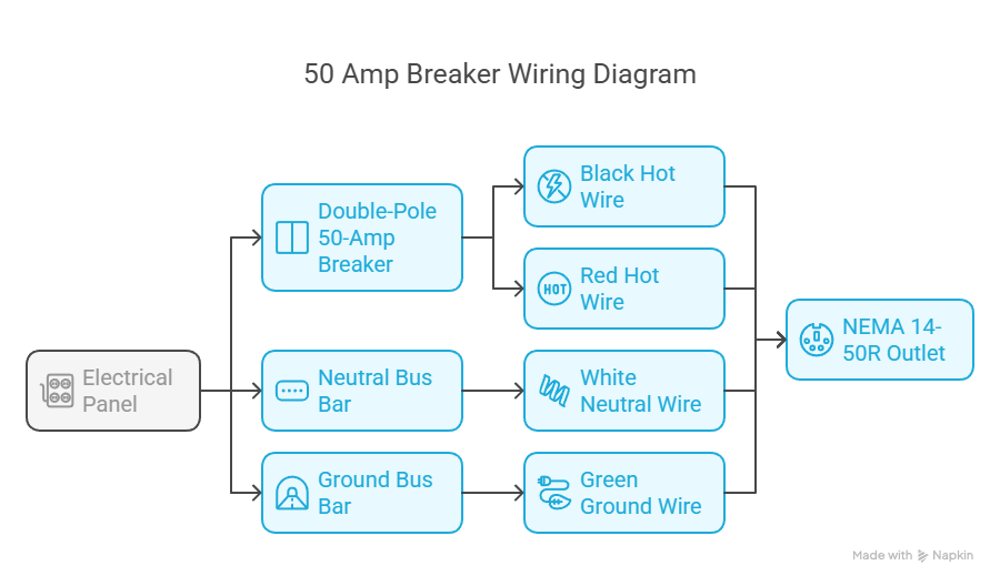
A 50 Amp breaker wiring diagram looks like a setup using four distinct wires with specific purposes. The hot wires are black and red, each carrying 120 volts, and connect directly to the two terminals of a double-pole 50-amp breaker inside the electrical panel. The neutral wire is white and connects to the neutral bus bar, while the ground wire is green or bare copper and connects to the ground bus bar. NEMA 14-50R outlets connect the black and red-hot wires to the two brass terminals, the white neutral wire to the silver terminal, and the green ground wire to the green grounding terminal. Each wire must be stripped to the proper length and fastened securely to ensure a strong and stable connection without risk of loosening.
Proper wire routing ensures a safe and reliable setup for heavy loads. A 4-conductor cable carries the wiring from the breaker panel to the outlet box, with the hot wires kept together to reduce electromagnetic interference, while the neutral and ground wires are routed separately to their bus bars. Wires must maintain gentle curves without sharp bends or kinks to avoid damage. All wire connections must be tightened securely to prevent overheating or electrical faults. A weatherproof outlet box is required for outdoor installations to protect against moisture and environmental damage. Power must be turned off at the main breaker before starting any work, and a voltage tester must be used to confirm the circuit is de-energized. Testing the completed setup with a multimeter verifies that voltage and polarity meet safety standards for reliable operation.
What is the Difference Between 3-Wire and 4-Wire 50 Amp RV Plugs?
The difference between 3-Wire and 4-Wire 50 Amp RV plugs lies in the wiring configuration and safety standards. A 3-wire plug has two hot wires and either a combined neutral and ground or just one neutral wire, which increases the risk of electrical faults due to the shared path. A 4-wire plug includes two hot wires, a separate neutral wire, and a dedicated ground wire, following the NEMA 14-50 standard used for modern RVs. The extra ground wire in the 4-wire plug creates a separate path for fault currents, significantly reducing the risk of electric shock and equipment damage. Separating the ground from the neutral ensures that the ground wire serves only as a safety mechanism, not a current carrier during regular operation, heightening the RV system’s electrical safety.
The 3-wire plugs were commonly used in older RVs and electrical systems, based on outdated codes that allowed neutral and ground sharing. Modern updates to electrical codes now require a clear separation between neutral and ground wires, making 3-wire plugs obsolete except in older setups. The 4-wire system offers advantages for contemporary RVs, such as improved safety, handling up to 12,000 watts to support multiple appliances, and more stable power distribution with balanced 120/240V output from the two hot wires. Using a 4-wire 50-amp RV receptacle ensures compliance with current electrical codes and compatibility with modern campgrounds and RV parks, supporting safer and more reliable RV operation.
Is a 50 Amp RV Plug 120V or 240V?
A 50 Amp RV plug operates on 240V, not 120V, providing significantly more power. The four-prong configuration (NEMA 14-50) consists of two 120V hot wires, a neutral wire, and a ground wire. The plug delivers 240V when measured across the two hot terminals, making it suitable for larger RVs with high-demand appliances, such as air conditioners, electric ovens, and washers.
The 50-amp RV plug’s 240V capability allows it to supply up to 12,000 watts, far exceeding the 3,600 watts provided by a 30-amp, 120V RV plug. The higher capacity enables multiple appliances to run simultaneously, unlike the 30-amp plug, which supports fewer appliances, like a television, a small refrigerator, and a microwave, due to its lower wattage and voltage.
U.S. household outlets provide 120V, while electric ranges and dryers use 240V circuits, similar to the 50-amp RV plug configuration. RV plugs are designed for RVs’ power needs and must not be substituted for standard household outlets. The 50-amp plug supports high-power appliances, whereas the 30-amp plug is limited to fewer, smaller appliances.
How Do 30 Amp to 50 Amp Adapters Work?
30-Amp to 50-Amp adapters work by allowing a 30-Amp RV to connect to a 50-Amp outlet found at campgrounds. The adapter has a 50-amp male plug on one end that fits into the 50-amp outlet and a 30-amp female socket on the other that connects to the RV’s power cord. The adapter only uses one of the two 120V hot legs from the 50-amp supply because a 30-amp RV uses a single 120V hot wire. The adapter does not increase the power available to the RV. It allows a connection and ensures the RV receives a maximum of 30 Amps or 3,600 watts instead of 50 Amps.
Matching the plug size and power rating ensures a secure and safe connection between the RV and the outlet. Using the correct adapter prevents the RV from drawing more amperage than it is designed to handle. It helps avoid electrical hazards. However, the RV remains limited to 30 Amps. Attempting to use more power than the RV’s capacity trips the main breaker or overheats the wiring. The adapter does not increase the RV’s power capacity. Avoid using appliances that exceed 30 Amps. Check for heat buildup and use surge protectors to protect the system from damage.
How Do You Test a 50 Amp RV Outlet with a Multimeter?
Test a 50 Amp RV Outlet with a multimeter by following the seven steps listed below.
- Set the Multimeter to AC Voltage. Turn the multimeter dial to the AC voltage setting, marked as “VAC” or “V~”, because RV outlets supply alternating current.
- Identify Outlet Terminals. Locate the four terminals on the 50-amp RV outlet. Two hot terminals are brass-colored and positioned opposite each other, one neutral terminal is silver-colored, and one ground terminal is green or bare.
- Test Voltage Between Hot Terminals. Insert one probe into each of the two hot slots. Check the reading, it must be around 240 volts. A significantly lower or zero reading suggests a wiring issue or that one leg is not powered, indicating a possible problem with the power supply.
- Test Voltage from Hot to Neutral. Insert one probe into a hot terminal and the other into the neutral terminal. Repeat for both hot terminals. Each reading must be around 120 volts. There are insufficient voltage, poor connections, or utility problems if readings exceed the 105–128 volts range. A 0-volt reading suggests reversed wiring or a disconnected neutral.
- Test Voltage from Hot to Ground. Insert one probe into a hot terminal and the other into the ground terminal. Repeat for both hot terminals. Each reading must show 120 volts. A reading lower than 120 volts suggests a faulty or disconnected ground.
- Test Voltage from Neutral to Ground. Insert one probe into the neutral terminal and the other into the ground terminal. The reading must be close to 0 volts, less than 5 volts. A higher reading indicates a grounding or neutral wiring problem, potentially caused by reversed wiring or improper connections.
- Check Continuity (Power Off). Turn off the circuit breaker for the outlet. Set the multimeter to continuity mode, marked by a sound wave or diode symbol. Touch one probe to the ground terminal and the other to the outlet’s metal chassis or a known ground. The meter must beep or show near-zero resistance, confirming a continuous ground path. Repeat the process between the neutral and ground. There must be no continuity (no beep), confirming that neutral and ground are not shorted together, indicating proper wiring.
How Do You Ground a 50 Amp RV Outlet?
Ground a 50 Amp RV outlet by ensuring proper grounding, essential for safety and system reliability. Grounding prevents electrical shocks by providing a safe path for fault currents. For instance, a hot wire touching a metal frame causes the ground wire to provide a secure path for the current to flow into the earth, which trips the breaker and prevents dangerous voltages from energizing exposed surfaces. Grounding protects equipment by diverting stray currents, such as currents caused by power surges or lightning strikes, away from sensitive devices.
Connecting the ground wire to a 50-amp RV outlet requires six steps. First, turn off the power at the main electrical panel to avoid electrical hazards. Second, mount the outlet in a weatherproof box at the desired location. Third, identify the terminals on the back of the outlet: two brass terminals for the hot wires, one silver terminal for the neutral wire, and one green terminal for the ground wire. Fourth, securely attach the bare or green ground wire to the green terminal. Fifth, double-check that all connections are tight. Lastly, use a voltage tester or multimeter to confirm the outlet is wired correctly and grounded before use.
Grounding the electrical panel is equally essential. The panel must have a ground bar connected to a grounding electrode, such as a ground rod driven into the earth, providing a direct path for fault currents. The neutral and ground must be bonded at a single point in the main service panel to allow the breakers to function correctly. The ground wire from the RV outlet must connect back to the panel’s ground bar, completing the grounding system.
Safety precautions are critical when grounding electrical systems. Turn off the power at the main panel before starting any electrical work. Use the correct gauge wire, typically 6 AWG for 50 amps, and ensure materials are rated for outdoor or wet locations if installed outside. Double-check all connections to avoid hazards like overheating or arcing. Consult a licensed electrician if unsure about any steps to prevent serious risks.
What Are the Common Wiring Mistakes to Avoid When Installing a 50 Amp RV Outlet?
The common wiring mistakes to avoid when installing a 50 Amp RV outlet are listed below.
- Using the wrong wire size: Using wire that is too small for a 50 amp circuit leads to voltage drop, overheating, and fire hazards. Copper wire of #6 AWG or aluminum wire of #4 AWG is required for most installations. Larger wires are necessary for longer runs.
- Improper grounding: Failing to securely attach the ground wire to the outlet’s green terminal increases the risk of electrical shock and equipment damage.
- Failing to tighten and maintain secure connections: Loose electrical connections cause arcing, overheating, or even fires. Vibration in RVs from travel loosens wires over time. Regular inspection and re-tightening of all terminals helps prevent RV Electrical Problems.
- Loose or poor connections: Loose connections cause arcing, overheating, and fires. Check and tighten connections regularly to prevent these risks.
- Damaged or misidentified wires: Using damaged wires or incorrectly labeled hot, neutral, and ground wires results in shorts, electric shock, or fire. Inspect wires for damage and ensure proper color coding.
- Improper tool use: Using the wrong tools results in poor connections or damaged hardware. Ensure the right tools are used for stripping, cutting, and connecting wires.
- Not following safe wiring rules or codes: Ignoring electrical codes or safety standards increases the risk of hazards. Follow local codes and consult a licensed electrician if unsure.
- Failure to Properly Test and Inspect the Outlet: Skipping final testing is a grave mistake that leads to equipment damage or injury. Use a multimeter or voltmeter to verify the correct voltage between hot and neutral (120V on each leg), 240V between hot legs, and no voltage between neutral and ground. Confirm all connections are secure and tight. Proper testing prevents RV Electrical Problems and ensures the outlet is safe before plugging in the RV.
- Bonding neutral and ground wires at the outlet: Neutral and ground must only be bonded at the main service panel. Connecting them to the RV outlet causes a stray current on the ground wire and creates a shock hazard.
What Are the Key Differences Between 50 Amp and 30 Amp RV Service?
The key difference between 50-amp and 30-amp RV service lies in power capacity. A 30-amp RV Plug provides up to 3,600 watts of power using a single 120-volt line, supporting basic electrical needs such as one air conditioner, microwave, or small appliances, but not simultaneously. A 50-amp service delivers up to 12,000 watts using two separate 120-volt lines, offering greater power capacity. It enables larger RVs to simultaneously operate several high-demand appliances, like dual air conditioners, washers, dryers, and residential refrigerators, without exceeding the power limit or tripping breakers.
The physical structure of the plugs differs as well. A 30-amp RV Plug has three prongs such as one hot wire, one neutral wire, and one ground wire. Its cylindrical shape is smaller and simpler. A 50-amp plug has four prongs, such as two hot wires, one neutral, and one ground, enabling split-phase power delivery. The larger size and extra prong in the 50 Amp plug accommodate higher capacity, ensuring it handles an increased electrical load.
RVs vary in their power needs based on size and appliance usage. Smaller and mid-sized RVs, travel trailers, and campers use the 30 Amp RV Plug because their electrical demands are lower. Larger RVs, fifth wheels, and luxury motorhomes require 50-amp service. Multiple high-power appliances run simultaneously on a 50-amp service without overloading the system, making for a more relaxing and convenient traveling experience.
Why is My 50 Amp RV Outlet Overheating?
Your 50 Amp RV outlet is overheating because of loose connections, inadequate wire size, or a faulty outlet. Loose or improperly tightened connections at the plug, outlet, or within the wiring create resistance, leading to heat buildup. Using too small wires for the electrical load increases resistance, causing excessive heat. Worn-out or corroded outlets or plugs develop increased resistance at connection points, contributing to overheating.
Overloading the circuit is another key cause of overheating. The total current draw exceeds the rated capacity of the outlet or wiring when more appliances or devices are plugged into the circuit than it safely handles. The excessive current flow generates more resistance and heat. A faulty circuit protection, like a breaker or fuse, quickly builds up heat, damaging the components and increasing the risk of fire or equipment failure.
Resolve overheating issues by inspecting all connections to ensure they are tight and secure. Check for signs of corrosion or damage to plugs, outlets, and extension cords, and replace affected components. Monitor that all wiring is sized appropriately for 50 amps to prevent overheating. Avoid overloading the circuit by monitoring the total power draw from appliances. Regular maintenance, such as cleaning contacts and using an infrared thermometer to monitor temperature, prevents overheating and ensures safe operation of the electrical system.
How Do You Replace a Damaged 50 Amp RV Plug?
Replace a damaged 40 Amp RV plug by following the nine steps listed below.
- Disconnect All Power Sources. Unplug the RV from any shore power and ensure the generator is completely turned off. Working on live electrical circuits leads to electric shock or serious injury.
- Gather Required Tools and Materials. Collect the necessary tools before starting, including wire cutters or lineman pliers, utility knife or razor knife, Phillips screwdriver, measuring tape, and a new 50-amp RV replacement plug (NEMA 14-50P). Optional items include gloves for hand protection and sealant for weatherproofing.
- Remove the Damaged Plug. Cut off the old or damaged plug several inches from the compromised section. Cut beyond any melted or heat-damaged parts to guarantee a clean starting point for the new installation.
- Prepare the Cable. Use a utility knife to strip the cable’s outer jacket about 3 inches (ca. 76 mm). Avoid damaging the insulation around the inner wires. Uncover four individual wires, such as black, red, white, and green.
- Trim and Strip the Wires. Shorten each wire according to the new plug’s specification. The green ground wire is left the longest, the white neutral the shortest, and the black and red hot wires in between. Strip approximately ½ inches (12 mm) of insulation from each wire to expose clean copper.
- Open the New Plug. Unscrew and open the new plug’s housing. Loosen or remove the cable clamp or strain relief section to allow room for wire positioning.
- Connect the Wires to the Plug Terminals. Attach the wires to their correct terminals. Green to the ground (marked “G” or “GRN”), white to the neutral (marked “W” or “WHT”), and black and red to the hot terminals (marked “X” and “Y” or “BLK” and “RED”). Use insulated tools and firmly tighten each terminal screw to avoid overheating or electrical arcing due to loose connections.
- Secure the Cable and Close the Plug. Position the heavy outer jacket of the cable securely in the clamp or strain relief to prevent tension on the wires. Close the plug casing and tighten all screws. Double-check that no copper is exposed and that each terminal is fastened correctly.
- Inspect and Test the Installation. Examine all connections to ensure no stray wire strands and that each wire is securely installed. Plug into a power source and test the plug’s functionality. Contact a certified electrician if unsure or lacking the necessary equipment to complete the task safely.
What Are the Best Wire Types for 50 Amp RV Outlets?
The best wire types for 50 Amp RV outlets are listed below.
- 6 AWG Copper Wire: 6 AWG Copper Wire delivers excellent electrical conductivity, allowing efficient power transfer with minimal energy loss. It is highly durable and corrosion-resistant, offering a longer service life and reduced maintenance. Stranded copper wire provides superior flexibility and is ideal for installations in tight or confined spaces. Its heavier weight and higher cost increase installation difficulty and expense. The 6 AWG size requires 50-amp RV circuits to carry current without overheating safely. Undersized copper wire results in voltage drop, fire hazards, or equipment damage. The 80% rule applies to continuous loads, meaning no more than 40 Amps must be drawn steadily.
- 4 AWG Aluminum Wire: 4 AWG Aluminum Wire is more affordable and lighter than copper, making it easier to install over long distances. Aluminum wire is flexible enough for various applications and is chosen for cost-sensitive or large-scale installations. Its lower conductivity requires a larger gauge to carry the same load, making 4 AWG necessary for 50-amp RV outlets. It is vulnerable to oxidation, so anti-oxidation compounds must be applied at terminals. Aluminum expands and contracts more than copper, making it essential to torque connections correctly to prevent loose terminals and sparking. Longer wire runs over 100 feet require upsizing to reduce voltage drop. Regular inspection is recommended to maintain safe operation.
What Are the Conduit Requirements for Outdoor Installations of a 50 Amp RV Outlet?
Conduit requirements for outdoor installations of a 50 Amp RV outlet include protective conduit to guard wiring, use of weather-rated materials like PVC or metal, and compliance with National Electrical Code (NEC) rules on conduit size and burial depth. The conduit requirements protect electrical wiring from physical damage, moisture, and environmental exposure. A conduit is a secure pathway that shields wires from lawn equipment, UV rays, weather, and other potential hazards. Electrical codes require conduit in exposed or underground outdoor locations to prevent insulation breakdown and reduce fire or shock risk. Weatherproof materials such as PVC Schedule 40 or 80 and metal conduit types like Electrical Metallic Tubing (EMT) or Rigid Metal Conduit (RMC) are commonly approved for these applications. Polyvinyl Chloride (PVC) is lightweight, corrosion-resistant, and easier to install, making it ideal for underground runs. Metal conduit provides stronger physical protection and is preferred in high-impact areas or when required by local regulations. Fittings and junction boxes must be rated for outdoor use and sealed properly to block water ingress.
The correct conduit size ensures smooth installation and safe operation. Wiring for 50-amp RV outlets includes two hot wires, one neutral, and one ground, using 6 AWG copper or 4 AWG aluminum. A minimum conduit diameter of 1 inch is recommended to accommodate four 6 AWG conductors comfortably, which helps prevent insulation damage during wire pulling. Underground conduit runs require a minimum burial depth of 18 to 24 inches, depending on the conduit type and local code. Proper conduit sizing and burial depth reduce the risk of overheating, physical damage, and system failure. Compliance with the NEC and regional regulations are essential, and consulting a licensed electrician ensures a safe and code-compliant installation.
Can I plug my 50 amp RV into 220V?
No, you cannot plug your 50 amp RV into 220V. A 50-amp RV plug is designed for a 240V NEMA 14-50 outlet, which provides two separate 120V hot wires. The two hot wires combine to deliver 240V total, supplying the correct voltage needed for RV systems. Standard 220V outlets do not provide the required configuration and lack the appropriate safety features for RV use.
The 240V outlet paired with 50 amps allows the RV to access up to 12,000 watts of power, supporting multiple high-demand appliances like air conditioners, ovens, and electric heaters simultaneously. The correct outlet ensures safe and efficient operation by matching voltage and amperage requirements. Plugging into the wrong outlet results in equipment damage or serious electrical hazards.
Can I plug my 50-amp RV into a 30 amp plug without damage?
Yes, you can plug your 50-amp RV into a 30-amp plug without damage using a compatible adapter, but the setup includes severe limitations. A 30-amp outlet delivers only 3,600 watts, far less than the 12,000 watts supported by a 50-amp service. The reduced capacity limits the ability to simultaneously run high-power appliances such as air conditioners, microwaves, or electric heaters. Overloading the system trips the breaker or causes overheating, increasing the fire risk if safeguards fail.
A 30-to-50 amp adapter enables physical connection without boosting electrical capacity or increasing protection. The 30-amp breaker at the pedestal remains the only line of defense. Exceeding the limit strain on the RV’s electrical system, especially if safety devices are inadequate or if the wrong type of extension cord is used. A surge protector adds an extra layer of security against power surges or overloads. Safe use depends on limiting total power draw and choosing a 50-amp outlet whenever possible.
Can I plug my 50 amp RV into a 30 Amp generator?
Yes, you can plug your 50 amp RV into a 30-amp generator, but significant limitations exist. A 50-amp RV requires up to 12,000 watts, while a 30-amp generator provides only about 3,600 watts. The power mismatch prevents the RV from running all appliances simultaneously at full capacity. Connecting the two power supplies requires a 30-amp (male) to 50-amp (female) adapter, known as a “dogbone” adapter. The adapter allows for the physical connection but does not increase the power supply.
The primary issue is the power supply mismatch. The RV only draws up to 30 amps at 120 volts, regardless of its 50 amp capacity. Running too many high-power appliances simultaneously, such as air conditioners or multiple devices, causes the generator’s breaker to trip or damage equipment due to overloading. Manage power usage to prevent exceeding the generator’s capacity.
A generator for a 30-amp RV is a better match for RVs that require 30 amps, as it provides adequate power for typical usage. A 30-amp generator only provides 30 amps to a 50-amp RV, ensuring no risk of overloading the RV’s system. Ensure the combined power draw of all appliances stays within the generator’s capacity to avoid any issues with a Generator for 30 Amp RV.